
Page 232 - Introduction to Information Optics
P. 232
4.2. All-Optical Switches 211
arrive at the SOA before the counterclockwise component. The difference in
the arrival time (i) depends on the amount of offset x. The role of the control
signal is to create a refractive index change by rapidly sweeping out some of
the gain of the SOA. Therefore, a pulse passing through the SOA before the
control pulse will experience different phase shift from the pulse passing
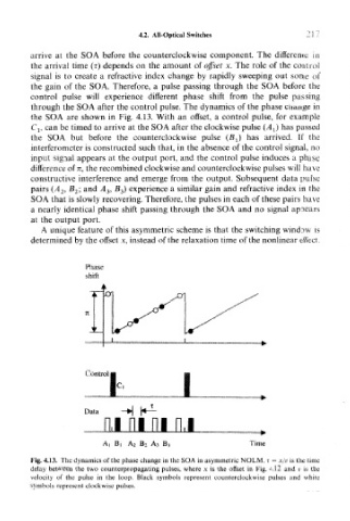
through the SOA after the control pulse. The dynamics of the phase change in
the SOA are shown in Fig. 4.13. With an offset, a control pulse, for example
C t , can be timed to arrive at the SOA after the clockwise pulse (A^ has passed
the SOA but before the counterclockwise pulse (BJ has arrived. If the
interferometer is constructed such that, in the absence of the control signal, no
input signal appears at the output port, and the control pulse induces a phase
difference of n, the recombined clockwise and counterclockwise pulses will have
constructive interference and emerge from the output. Subsequent data pulse
pairs (A 2, B 2l and A 3, B 3) experience a similar gain and refractive index in the
SOA that is slowly recovering. Therefore, the pulses in each of these pairs have
a nearly identical phase shift passing through the SOA and no signal appears
at the output port.
A unique feature of this asymmetric scheme is that the switching window is
determined by the offset x, instead of the relaxation time of the nonlinear effect.
Phase-
shift
i
Control
m
Data
ni ni n.i
At Bi A 2 B 2 A 3 Bj Time
Fig. 4.13. The dynamics of the phase change in the SOA in asymmetric NOLM. T = x/v is the time
delay between the two counterpropagating pulses, where x is the offset in Fig. 4.12 and v is the
velocity of the pulse in the loop. Black symbols represent counterclockwise pulses and white
symbols represent clockwise pulses.