
Page 236 - Introduction to Information Optics
P. 236
4.3. Fast Electro-optic Switches: Modulators 221
and theoretical investigations have been presented in numerous publications.
Considerable attention has been paid to increasing the modulation bandwidth
of diode lasers. In this section, we discuss the factors that limit the modulation
bandwidth of diode lasers.
4.3.1.1. Small-Signal Modulation Response
When the modulation depths of the drive current and optical output are
substantially less than 1, we call this small-signal modulation. A simplified
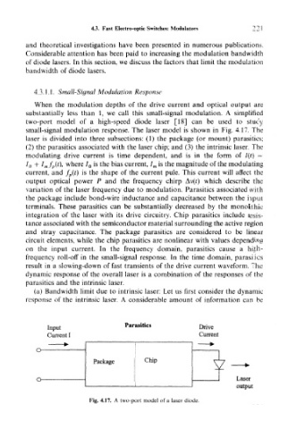
two-port model of a high-speed diode laser [18] can be used to study
small-signal modulation response. The laser model is shown in Fig. 4.17. The
laser is divided into three subsections: (1) the package (or mount) parasitics;
(2) the parasitics associated with the laser chip; and (3) the intrinsic laser. The
modulating drive current is time dependent, and is in the form of I(t) =
7 0 + I mf p(t), where / 0 is the bias current, I m is the magnitude of the modulating
current, and f p(t) is the shape of the current pule. This current will affect the
output optical power P and the frequency chirp Av(?) which describe the
variation of the laser frequency due to modulation. Parasitics associated with
the package include bond-wire inductance and capacitance between the input
terminals. These parasitics can be substantially decreased by the monolithic
integration of the laser with its drive circuitry. Chip parasitics include resis-
tance associated with the semiconductor material surrounding the active region
and stray capacitance. The package parasitics are considered to be linear
circuit elements, while the chip parasitics are nonlinear with values depending
on the input current. In the frequency domain, parasitics cause a high-
frequency roll-off in the small-signal response. In the time domain, parasitics
result in a slowing-down of fast transients of the drive current waveform. The
dynamic response of the overall laser is a combination of the responses of the
parasitics and the intrinsic laser.
(a) Bandwidth limit due to intrinsic laser: Let us first consider the dynamic
response of the intrinsic laser. A considerable amount of information can be
Input Parasitics Drive
Current I Current
O
Package j cl »P
O Laser
output
Fig. 4.17. A two-port model of a laser diode.