
Page 492 - Introduction to Information Optics
P. 492
9.2. Parallel Optical Logic and Architectures 4/7
performance parallel computing systems. Since optical interconnections and
neural networks will be discussed elsewhere in this book, this chapter focuses
on parallel optical architectures and algorithms suitable for optical implemen-
tation. Parallel optical logic and architectures will be presented in Sec. 9.2.
followed by a review of various number systems and arithmetic operations in
Sec. 9.3. Section 9.4 is focused on parallel signed-digit algorithms, and number
conversion is discussed in Sec. 9.5. Several optical implementation examples are
given in Sec. 9.6, and a summary is presented in Sec. 9.7.
9.2. PARALLEL OPTICAL LOGIC AND ARCHITECTURES
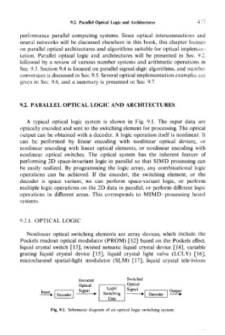
A typical optical logic system is shown in Fig. 9.1. The input data are
optically encoded and sent to the switching element for processing. The optical
output can be obtained with a decoder. A logic operation itself is nonlinear. It
can be performed by linear encoding with nonlinear optical devices, or
nonlinear encoding with linear optical elements, or nonlinear encoding with
nonlinear optical switches. The optical system has the inherent feature of
performing 2D space-invariant logic in parallel so that SIMD processing can
be easily realized. By programming the logic array, any combinational logic
operations can be achieved. If the encoder, the switching element, or the
decoder is space variant, we can perform space-variant logic, or perform
multiple logic operations on the 2D data in parallel, or perform different logic
operations in different areas. This corresponds to MIMD- processing based
systems.
9.2.1. OPTICAL LOGIC
Nonlinear optical switching elements are array devices, which include the
Pockels readout optical modulator (PROM) [12] based on the Pockels effect,
liquid crystal switch [13], twisted nematic liquid crystal device [14], variable
grating liquid crystal device [15], liquid crystal light valve (LCLV) [16],
microchannel spatial-light modulator (SLM) [17], liquid crystal televisions
Encoded Switched
Optical Optical
Logic Signal
S Signal Mgnai r
nal
Input I 1 'g o u I 1 Output
Switching
."ESV Encoder — » Switching *\ Decode *->
Decoderr
Encoder
Unit
I Unit j
Fig. 9.1. Schematic diagram of an optical logic switching system.