
Page 493 - Introduction to Information Optics
P. 493
9. Computing with Optics
t* 1 v
*t t + * W
1 LCC
1*
4 t ^ |
^ t
A.B
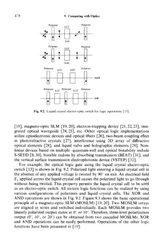
Fig. 9.2. Liquid crystal electro-optic switch for logic operations [13].
[18], magneto-optic SLM [19,20], electron-trapping device [21,22,23], inte-
grated optical waveguide [24,25], etc. Other optical logic implementations
utilize optoelectronic devices and optical fibers [26], two-beam coupling effect
in photorefractive crystals [27], interference using 2D array of diffractive
optical elements [28], and liquid valve and holographic elements [29]. Non-
linear devices based on multiple- quantum-well and optical bistability include
S-SEED [8,30], bistable etalons by absorbing transmission (BEAT) [31], and
the vertical surface transmission electrophotonic device (VSTEP) [32].
For example, the optical logic gate using the liquid crystal electro-optic
switch [13] is shown in Fig. 9.2. Polarized light entering a liquid crystal cell in
the absence of any applied voltage is twisted by 90° on exit. An electrical field
£j applied across the liquid crystal cell causes the polarized light to go through
without being twisted. This property permits the liquid crystal cell to be used
as an electro-optic switch. All sixteen logic functions can be realized by using
various configurations of polarizers and liquid crystal cells. The XOR and
AND operations are shown in Fig. 9.2. Figure 9.3 shows the basic operational
principle of a magneto-optic SLM (MOSLM) [19,20]. Two MOSLM arrays
are aligned in series and switched individually. Each MOSLM provides two
linearly polarized output states at 0° or 10°. Therefore, three-level polarization
output (0°, 10°, or 20°) can be obtained from two cascaded MOSLMs. XOR
and AND operations can be easily performed. Operations of the other logic
functions have been presented in [19].