
Page 494 - Introduction to Information Optics
P. 494
9.2. Parallel Optical Logic and Architectures 479
Output light o
PoiarizatkMi»0
MOSLM-1 0 MOSLM-2
ROTATION-0 ROTATION-0
^ k ^
^1 ^ ?/ Output HgM o
^ /. / Ptoarizatton-IO
^ ^
^ ^
MOSLM-1 o MOSLM-2 o
ROTATION-10 ROTATION-0
^ \ ^
1
^ ^ ! 7 Output light
\j Polarization-ID
^ ^
,_ — *fcj I r
^
MOSLM-1 , MOSLM-2
ROTATIONS) ROTATION-10
1. !«>/Output light 0
Polarization-20
/
^
^ ^^
MOSLM-1 o MOSLM-2 o
ROTATIOf*«10 ROTATION-10
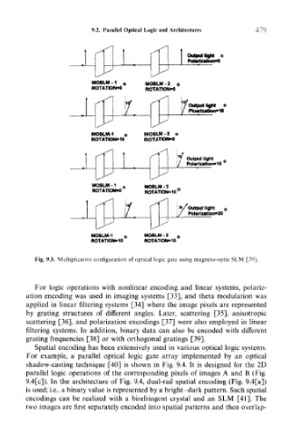
Fig. 9.3. Multiplicative configuration of optical logic gate using magneto-optic SLM [20].
For logic operations with nonlinear encoding and linear systems, polariz-
ation encoding was used in imaging systems [33], and theta modulation was
applied in linear filtering systems [34] where the image pixels are represented
by grating structures of different angles. Later, scattering [35], anisotropic
scattering [36], and polarization encodings [37] were also employed in linear
filtering systems. In addition, binary data can also be encoded with different
grating frequencies [38] or with orthogonal gratings [39].
Spatial encoding has been extensively used in various optical logic systems.
For example, a parallel optical logic gate array implemented by an optical
shadow-casting technique [40] is shown in Fig. 9.4. It is designed for the 2D
parallel logic operations of the corresponding pixels of images A and B (Fig.
9.4[c]). In the architecture of Fig. 9.4, dual-rail spatial encoding (Fig. 9.4[a])
is used; i.e., a binary value is represented by a bright-dark pattern. Such spatial
encodings can be realized with a birefringent crystal and an SLM [41]. The
two images are first separately encoded into spatial patterns and then overlap-