
Page 646 - Introduction to Information Optics
P. 646
630 11. Information Display with Optics
Krypton-Argon laser for R,G,B source
Collimating lenses Focusing Senses
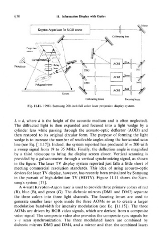
Fig. 11.11. 1998's Samsung 200-inch full color laser projection display system.
L » d, where d is the height of the acoustic medium and is often neglected).
The diffracted light is then expanded and focused into a light wedge by a
cylinder lens while passing through the acousto-optic deflector (AOD) and
then restored to its original circular form. The purpose of forming the light
wedge is to increase the number of resolvable angles along the horizontal scan
line (see Eq. [11.17]). Indeed, the system reported has produced N — 200 with
a sweep signal from 19 to 35 MHz. Finally, the deflection angle is magnified
by a third telescope to bring the display screen closer. Vertical scanning is
provided by a galvanometer through a vertical synchronizing signal, as shown
in the figure. The laser TV display system reported just falls a little short of
meeting commercial resolution standards. This idea of using acousto-optic
devices for laser TV display, however, has recently been revitalized by Samsung
in the pursuit of high-definition TV (HDTV). Figure 11.11 shows the Sam-
sung's system [17].
A 4-watt Krypton-Argon laser is used to provide three primary colors of red
(R), blue (B), and green (G). The dichroic mirrors (DM1 and DM2) separate
the three colors into three light channels. The focusing lenses are used to
generate smaller laser spots inside the three AOMs so as to create a larger
modulation bandwidth for intensity modulation (see Eq. [11.15]). The three
AOMs are driven by RGB video signals, which are derived from a composite
video signal. The composite video also provides the composite sync signals for
x-y scan synchronization. The three modulated lasers are combined by
dichroic mirrors DM3 and DM4, and a mirror and then the combined lasers