
Page 647 - Introduction to Information Optics
P. 647
11.2. Information Display Using Acousto-Optic Spatial Light Modulators 631
are scanned by a rotating polygonal mirror for horizontal lines and a
galvanometer for vertical lines. Finally, the 2-D scanning image is projected by
a projection mirror on a screen for 2-D display. Note that even though the
polygonal scan mirror is synchronized by the horizontal sync signal derived
from the composite video, it is still necessary to correct the jittering due to the
mirror's fast rotating speed. The correction is done by monitoring a reflected
beam from the polygonal mirror, where the reflected light is derived from the
first order diffracted light of one of the AOMs, as shown in the figure (see the
dotted line). A photodiode detecting the deviation of the position of the
reflected light together with some kind of feedback circuit delivers a correcting
signal to the polygonal mirror. It is interesting to point out that this kind of
feedback mechanism to compensate for any joggling of the mirror is not
necessary if an acousto-optic deflector for horizontal scanning is used, as in
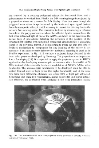
Zenith's experiment. In Fig. 11.12, we show a projected image obtained by the
laser video projector developed by Samsung. The projection is an impressive
4 m x 3 m display [18]. It is expected to apply the projector system to HDTV
applications by developing acousto-optic modulators with a bandwidth of 30
MHz instead of the currently developed modulators of NTSC's 5-Mhz video
bandwidth. The acousto-optic modulators to be developed must be able to
sustain focused lasers of high power (for higher bandwidth) and at the same
time have high diffraction efficiency; say, about 80% of light gets diffracted.
Remember that these two requirements, higher bandwidth and higher diffrac-
tion efficiency, are conflicting when analyzed in the weak interaction regime
Fig. 11.12. Two hundred-inch full color laser projection display (courtesy of Samsung Advance
Institute of Technology [18]).