
Page 105 - Introduction to Marine Engineering
P. 105
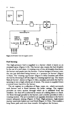
92  Boilers


                      To burners
                 Figure 4.15 Boiler fuel-oil  supply system


                 Fuel  burning

                 The  high-pressure  fuel  is  supplied  to  a  burner  which  it  leaves  as an
                 atomised spray  (Figure 4.16). The  burner  also rotates the fuel  droplets
                 by the use of a swirl plate. A rotating cone of tiny oil droplets thus leaves
                 the burner  and  passes into the furnace. Various designs of burner  exist,
                 the  one just  described  being  known  as a  'pressure jet  burner'  (Figure
                 4.16(a». The  'rotating cup burner' (Figure 4.14(b)) atomises  and  swirls
                 the fuel by throwing it off the edge of a rotating tapered cup. The  'steam
                 blast jet burner', shown in Figure  4.16(c), atomises and swirls the fuel by
                 spraying it into a high-velocity jet  of steam. The  steam is supplied down
                 a central inner  barrel  in the  burner.
                   The  air  register  is a  collection  of  flaps,  vanes,  etc.,  which  surrounds
                 each  burner  and  is  fitted  between  the  boiler  casings.  The  register
                 provides  an  entry  section  through  which  air  is  admitted  from  the
                 windbox. Air shut-off is achieved by means of a sliding sleeve or  check.
                 Air flows through  parallel to the burner,  and a swirler provides it with a
                 rotating motion. The air is swirled in an opposite direction to the fuel to
                 ensure  adequate  mixing  (Figure  4.17(a)).  High-pressure,  higb-0i»tput
                 marine watertube boilers are roof  fired  (Figure 4.17(b)). This enables a
                 long flame  path and  even heat transfer throughout  the furnace.