
Page 338 - Introduction to Marine Engineering
P. 338
312 Instrumentation and control
The problems associated with swell and shrinkage are removed by the
use of a second measuring element, 'steam flow'. A third element, 'feed
water flow', is added to avoid problems that would occur if the feed
water pressure were to vary.
A three element control system is shown in Figure 15.$6. The
measured variables or elements are 'steam flow', 'drum level* and 'feed
water flow*. Since in a balanced situation steam flow must equal feed
flow, these two signals are compared in a differential relay. The relay
output is fed to a two-term controller and comparator into which the
measured drum level signal is also fed. Any deviation between the
desired and actual drum level and any deviation between feed and steam
flow will result in controller action to adjust the feed water control valve.
The drum level will then be returned to its correct position.
A sudden increase in steam demand would result in a deviation signal
from the differential relay and an output signal to open the feed water
control valve. The swell effect would therefore not influence the correct
operation of the control system. For a reduction in steam demand, an
output signal to close the feedwater control valve would result, thus
avoiding shrinkage effects. Any change in feed water pressure would
result in feed water control valve movement to correct the change before
the drum level was affected.
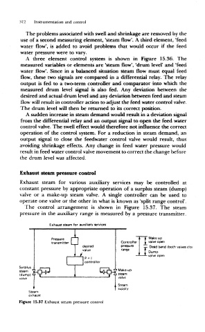
Exhaust steam pressure control
Exhaust steam for various auxiliary services may be controlled at
constant pressure by appropriate operation of a surplus steam (dump)
valve or a make-up steam valve, A single controller can be used to
operate one valve or the other in what is known as 'split range control*.
The control arrangement is shown in Figure 15.37. The steam
pressure in the auxiliary range is measured by a pressure transmitter.
Exhaust steam for auxiliary services
JL "
Pressure I n Make up
transmitter | | Controller valve open
J desired pressure Dead band {both valves cloj
value range
Dump
ii * valve open
P + 1
controller
Surplus • i * >
steam \Lrt-U LurHA ' Make up
(dump) A Y "^ i '* Y 21 steam
valve
Steam
supply
Steam
exhaust
Figure 15.37 Exhaust steam pressure control