
Page 81 - Introduction to Marine Engineering
P. 81
68 Steam turbines and gearing
Planetary Propeller shaft Planetary Fixed annulus
§ ear ^ Rotating sunwhee^
Rotating Rotating planet-carrier
Rotating planet-carrier
sun wheel Planet wheels rotating
annul us) about own spindles
Inion shaft
Planet wheels
rotating about
own spindles
Pinion
Parallel shaft .
reduction gear Low-pressure
Star gear a turbine input
^
Rotating annulus
Rotating sunwheel
Starwheels rotating
about own spindles
High-pressure
turbine input
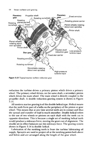
Figure 3.13 Typical marine turbine reduction gear
reduction the turbine drives a primary pinion which drives a primary
wheel. The primary wheel drives, on the same shaft, a secondary pinion
which drives the main wheel. The main wheel is directly coupled to the
propeller shaft. A double reduction gearing system is shown in Figure
3.14.
All modern marine gearing is of the double helical type. Helical means
that the teeth form part of a helix on the periphery of the pinion or gear
wheel. This means that at any time several teeth are in contact and thus
the spread and transfer of load is much smoother. Double helical refers
to the use of two wheels or pinions on each shaft with the teeth cut in
opposite directions. This is because a single set of meshing helical teeth
would produce a sideways force, moving the gears out of alignment. The
double set in effect balances out this sideways force. The gearing system
shown in Figure 3.14 is double helical.
Lubrication of the meshing teeth is from the turbine lubricating oil
supply. Sprayers are used to project oil at the meshing points both above
and below and are arranged along the length of the gear wheel.