
Page 69 - Introduction to Microcontrollers Architecture, Programming, and Interfacing of The Motorola 68HC12
P. 69
46 Chapter 2 The Instruction Set
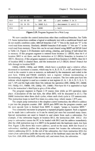
Figure 2.19. Program Segment for a Wait Loop
We now consider the control instructions other than conditional branches. See Table
2.9. Some instructions combine a logical or arithmetic test with a conditional branch and
do not modify condition codes. BRCLR branches if all "1" bits in the mask are "0" in the
word read from memory. Similarly, BRSET branches if all masks "1" bits are "1" in the
word read from memory. These bits can be set and cleared using BSET and BCLR listed
in Table 2.6. Figure 2.18 illustrates such setting, clearing, and testing of individual bits
in memory. If this program segment is entered from location LI ($820), then bit 6 of
location $802 is set there, and the instruction at L3 ($82A) branches to location L4
($831). However, if this program segment is entered from location L2 ($826), then bit 6
of location $802 is cleared there, and the instruction at L3 ($82A) doesn't branch but
Mis through to location $82F.
DBEQ, DBNE, IBEQ, and IBNE, which have a postbyte and a relative offset,
decrement or increment a counter, which may be A, B, D, X, Y, or SP, and branch if the
result in the counter is zero or nonzero, as indicated by the mnemonic and coded in the
post byte. TBEQ and TBNE similarly test a register without incrementing or
decrementing it and branch if the result is zero or nonzero. The low-order post byte bits
indicate which register is used as a counter or test register (0, A; 1, B; 4, D; 5, X; 6, Y;
and 7, SP) and the high-order three bits indicate the operation (000, DBEQ; 001, DBNE;
010, TBEQ; Oil, TBNE; 100, IBEQ; 101, IBNE). Post-byte bit 4 is appended as high
bit to the instruction's third byte to give a 9-bit offset.
The program segment in Figure 2.19 wastes time while an I/O operation takes
place. (Calculation of the last byte, the offset $FD, will be discussed in §3.3.) The
DBNE instruction takes three clock cycles, where each clock cycle is 125 nanoseconds.
This instruction loops to itself five times in a delay loop, which wastes 1.875 us&c.
The simple jump instruction is the simplest control instruction; the effective address
is put into the program counter. JMP $899 puts $899 into the program counter, and
the next opcode byte is fetched from $899. It simply "jumps to location $899."
You commonly encounter in programs a repeated program segment. Such a segment
can be made into a subroutine so it can be stored just once but executed many times.
Special instructions are used to branch to and return from such a subroutine. For
example, if the subroutine begins at location $812, the instruction JSR $812 (for
jump to subroutine) causes the PC to be loaded with $812 and the address immediately
after the JSR instruction (say it is $807) to be pushed onto the hardware stack, low byte
first. Figure 2.20a shows this return address, saved on the stack. BSR (for branch to
subroutine) similarly pushes the program counter but locates the subroutine using
relative addressing (§3.3). At the end of the subroutine, the 1-byte instruction RTS (for
return from subroutine) pulls the top two bytes of the hardware stack into the PC, high
byte first. JSR, SUB, and RTS, efficiently call, and return from, the subroutine.