
Page 70 - Introduction to Microcontrollers Architecture, Programming, and Interfacing of The Motorola 68HC12
P. 70
2,3 Control Instructions 47
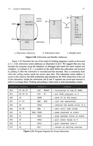
Figure 2.20. Subroutine and Handler Addresses
Figure 2.20 illustrates the use of the stack for holding temporary results as discussed
in 2.1, with subroutine return addresses as illustrated in §2.5. We suggest that you step
through this program using the simulator or debugger and watch the stack expand and
compress. A constant in X, 1, is pushed on the stack before the subroutine and restored
by pulling X after the subroutine is executed and has returned. This is commonly done
when the calling routine needs the saved value later. The subroutine return address is
saved on the stack by the BSR instruction and restored by the RTS instruction at the end
of the subroutine. Inside the subroutine, the X and Y registers are saved and restored in
order to exchange them. Pushing and pulling is often done to hold intermediary results.
Figure 221. Program Segment for Swap Subroutine