
Page 251 - Introduction to Naval Architecture
P. 251
236 PROPULSION
as the propeller revolutions and slip increase. Tip vortex cavitation is
next to appear, resulting from the low pressure within the tip vortex, As
the pressure on the back of the blade falls further the cavitation extends
from the leading edge across the back until there is a sheet of cavitation.
When the sheet covers the whole of the back of the blade the propeller is
said to be fully cavitating or super-cavitating. Propellers working in this
range do not experience erosion on the back and the drag due to the
frictional resistance to flow over the back disappears. Thus when fairly
severe cavitation is likely to occur anyway there is some point in going to
the super-cavitation condition as the design aim. Super-cavitating propellers
are sometimes used for fast motor boats.
Flat faced, circular back sections tend to have a less peaky pressure
distribution than aerofoil sections. For this reason they have often been
used for heavily loaded propellers. However, aerofoil sections can be
designed to have a more uniform pressure distribution and this
approach is to be preferred. For a given thrust, more blades and
greater blade area will reduce the average pressures and therefore the
peaks. It will be found that heavily loaded propellers have much
broader blades than lightly loaded ones.
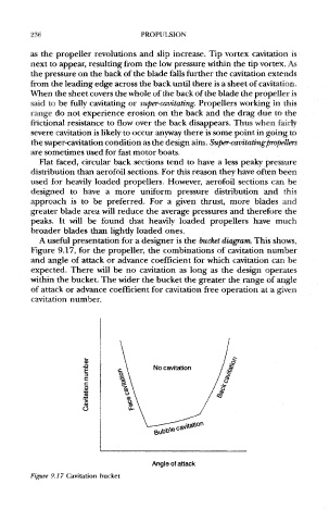
A useful presentation for a designer is the bucket diagram. This shows,
Figure 9.17, for the propeller, the combinations of cavitation number
and angle of attack or advance coefficient for which cavitation can be
expected. There will be no cavitation as long as the design operates
within the bucket. The wider the bucket the greater the range of angle
of attack or advance coefficient for cavitation free operation at a given
cavitation number.
Figure 9,17 Cavitation bucket