
Page 252 - Introduction to Naval Architecture
P. 252
PROPULSION 237
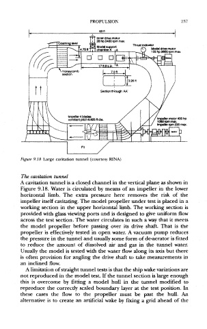
Figure 9.18 Large cavitation tunnel (courtesy RINA)
The cavitation tunnel
A cavitation tunnel is a closed channel in the vertical plane as shown in
Figure 9.18. Water is circulated by means of an impeller in the lower
horizontal limb. The extra pressure here removes the risk of the
impeller itself cavitating. The model propeller under test is placed in a
working section in the upper horizontal limb. The working section is
provided with glass viewing ports and is designed to give uniform flow
across the test section. The water circulates in such a way that it meets
the model propeller before passing over its drive shaft. That is the
propeller is effectively tested in open water. A vacuum pump reduces
the pressure in the tunnel and usually some form of de-aerator is fitted
to reduce the amount of dissolved air and gas in the tunnel water.
Usually the model is tested with the water flow along its axis but there
is often provision for angling the drive shaft to take measurements in
an inclined flow.
A limitation of straight tunnel tests is that the ship wake variations are
not reproduced in the model test. If the tunnel section is large enough
this is overcome by fitting a model hull in the tunnel modified to
reproduce the correctly scaled boundary layer at the test position. In
these cases the flow to the propeller must be past the hull. An
alternative is to create an artificial wake by fixing a grid ahead of the