
Page 253 - Introduction to Naval Architecture
P. 253
238 PROPULSION
model propeller. The grid would be designed so that it reduced the
water velocities differentially to produce the correctly scaled wake
pattern for the hull to which the propeller is to be fitted.
Cavitation tunnel tests
Experiments are usually conducted as follows:
(1) The water speed is made as high as possible to keep Reynolds'
number high and reduce scaling effects due to friction on the
blades. Since wave effects are not present and the hull itself is
not under test the Froude number can be varied.
(2) The model is made to the largest possible scale consistent with
avoiding tunnel wall effects.
(3) The shaft revolutions are adjusted to give the correct advance
coefficient.
(4) The tunnel pressure is adjusted to give the desired cavitation
number at the propeller axis.
(5) A series of runs are made over a range of shaft revolutions, that
being a variable which is easy to change. This gives a range of
advance coefficients. Tests can then be repeated for other
cavitation numbers.
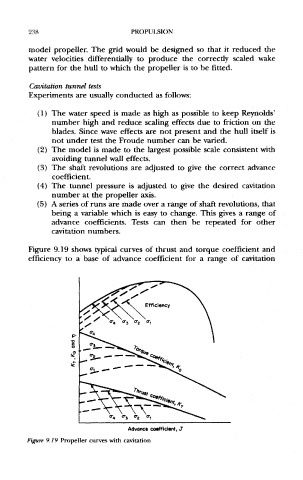
Figure 9.19 shows typical curves of thrust and torque coefficient and
efficiency to a base of advance coefficient for a range of cavitation
Figure 9,19 Propeller curves with cavitation