
Page 248 - Introduction to Naval Architecture
P. 248
PROPULSION 233
model tests. The model is fitted with propellers which are driven through
a dynamometer which registers the shaft thrust, torque and revolutions.
With the model being towed along the tank at its corresponding speed
for the ship speed under study, the propellers are run at a range of
revolutions straddling the self-propulsion point for the model. The
model would already have been run without propellers to find its
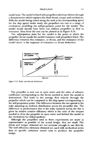
resistance. Data from the test can be plotted as in Figure 9.16.
The self-propulsion point for the model is the point at which the
propeller thrust equals the model resistance with propellers fitted. The
difference between this resistance, or thrust, and the resistance of the
model alone, is the augment of resistance or thrust deduction.
Figure 9.16 Wake and thrust deduction
The propeller is now run in open water and the value of advance
coefficient corresponding to the thrust needed to drive the model is
determined. This leads to the average flow velocity through the
propeller which can be compared to the ship speed corresponding to
the self-propulsion point. The difference between the two speeds is the
wake assuming an uniform distribution across the propeller disc. The
difference in performance due to the wake variation across the disc is
given by relative rotative efficiency which is the ratio of the torques
needed to drive the propeller in open water and behind the model at
the revolutions for self-propulsion.
Although the propellers used in these experiments are made as
representative as possible of the actual design, they are small. The
thrust and torque obtained are not accurate enough to use directly.
The hull efficiency elements obtained are used with methodical series
data or specific cavitation tunnel tests to produce the propeller
design.