
Page 229 - Introduction to Petroleum Engineering
P. 229
216 UPSTREAM FACILITIES
Example 11.7 Friction Factor
Calculate friction factor for fluid flowing through a pipe. Assume the relative
roughness of the pipe wall is 0.00014 and Reynolds number = 13 800.
Answer
Friction factor is calculated from Equation 11.27:
.
1 21 25
1142log 0 00014
.
.
f 13800 09 .
.
Solving gives f 0 0287.
11.5 MULTIPHASE FLOW IN PIPE
The description of single‐phase fluid flow in pipes presented earlier is relatively
simple compared to multiphase flow. In particular, two‐phase flow is characterized
by the presence of flow regimes or flow patterns. The flow pattern represents the
physical distribution of gas and liquid phases in the flow conduit. Forces that
influence the distribution of phases include buoyancy, turbulence, inertia, and surface
tension. The relative magnitude of these forces depends on flow rate, the diameter of
the conduit, its inclination, and the fluid properties of the flowing phases.
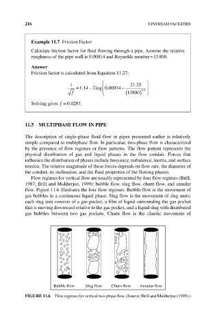
Flow regimes for vertical flow are usually represented by four flow regimes (Brill,
1987; Brill and Mukherjee, 1999): bubble flow, slug flow, churn flow, and annular
flow. Figure 11.6 illustrates the four flow regimes. Bubble flow is the movement of
gas bubbles in a continuous liquid phase. Slug flow is the movement of slug units;
each slug unit consists of a gas pocket, a film of liquid surrounding the gas pocket
that is moving downward relative to the gas pocket, and a liquid slug with distributed
gas bubbles between two gas pockets. Churn flow is the chaotic movement of
Bubble flow Slug flow Churn flow Annular flow
FIgURE 11.6 Flow regimes for vertical two‐phase flow. (Source: Brill and Mukherjee (1999).)