
Page 233 - Introduction to Petroleum Engineering
P. 233
220 UPSTREAM FACILITIES
(a)
Direct line-drive pattern
• • • • •
a = distance between
neighboring wells
d = distance between rows
of wells • • • • •
• Denotes production well
Denotes injection well • • • • •
(b)
Staggered line-drive
pattern • • • • •
a = distance between
neighboring wells
d = distance between • • • • •
rows of wells
• Denotes production well
Denotes injection well • • • • •
(c)
Five-spot pattern
• • •
d = distance between
neighboring producers • •
= distance between
neighboring injectors • • •
• •
• Denotes production well
Denotes injection well • • •
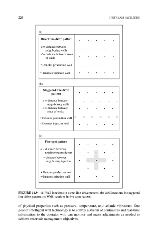
FIgURE 11.9 (a) Well locations in direct line‐drive pattern. (b) Well locations in staggered
line‐drive pattern. (c) Well locations in five‐spot pattern.
of physical properties such as pressure, temperature, and seismic vibrations. One
goal of intelligent well technology is to convey a stream of continuous and real‐time
information to the operator who can monitor and make adjustments as needed to
achieve reservoir management objectives.