
Page 285 - Introduction to Petroleum Engineering
P. 285
RESERVOIR FLOW SIMULATORS 273
Production wells Injection
wells
No-flow nodes
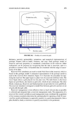
FIgURE 14.1 Overlay of a reservoir grid.
thickness, porosity, permeability, saturations, and numerical representations of
geologic features such as faults, fractures, and vugs. Each geologic model of
reservoir and rock properties is considered a realization of the reservoir. Other
realizations can be prepared by recognizing that the data is uncertain, and it is
possible to construct other 3‐D models that are consistent with the range of uncer‑
tainty of the data.
Reservoir flow simulators are used to model fluid flow in the reservoir, which is
based on the geologic model. A numerical representation of the geologic model is
used in the reservoir flow simulator. Figure 14.1 illustrates the procedure for digi‑
tizing the reservoir. The upper figure is a plan view of a reservoir with four wells. The
lower figure shows a grid placed over the plan view. The dark blocks in the lower
figure are grid blocks, also known as grid cells, which do not contain pay. The other
blocks contain pay. Reservoir and fluid properties are provided for every grid block.
The reservoir simulator is designed to model flow between grid cells and into or out
of grid cells through wells.
Reservoir management is most effective when as much relevant data as possible
is collected and integrated into a reservoir management study. The preparation of a
reservoir flow model can help an asset management team coordinate the acquisition
of the resources needed to determine the optimum plan for operating a field. If reser‑
voir flow model performance is especially sensitive to a particular parameter, then a
plan should be made to minimize or quantify uncertainty in the parameter.