
Page 296 - Introduction to Petroleum Engineering
P. 296
284 RESERVOIR PERFORMANCE
Plan view
Stimulated
Well pad
region
FIgURE 14.10 Sketch of wellbore trajectories drilled from a shale development well pad.
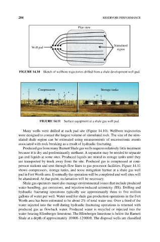
Compressors Storage tanks
FIgURE 14.11 Surface equipment at a shale gas well pad.
Many wells were drilled at each pad site (Figure 14.10). Wellbore trajectories
were designed to contact the largest volume of stimulated rock. The size of the stim‑
ulated shale region can be estimated using measurements of microseismic events
associated with rock breaking as a result of hydraulic fracturing.
Produced gas from many Barnett Shale gas wells requires relatively little treatment
because it is dry and predominantly methane. A separator may be needed to separate
gas and liquids at some sites. Produced liquids are stored in storage tanks until they
are transported by truck away from the site. Produced gas is compressed at com‑
pressor stations and sent through flow lines to gas processor facilities. Figure 14.11
shows compressors, storage tanks, and noise mitigation barrier at a shale gas well
pad in Fort Worth area. Eventually the operation will be completed and well sites will
be abandoned. At that point, reclamation will be necessary.
Shale gas operators must also manage environmental issues that include produced
water handling, gas emissions, and injection‐induced seismicity (IIS). Drilling and
hydraulic fracturing operations typically use approximately three to five million
gallons of water per well. Water used for shale gas production operations in the Fort
Worth area has been estimated to be about 2% of total water use. Over a third of the
water injected into the well during hydraulic fracturing operations is returned with
produced gas as flowback water. Produced water is recycled or injected into the
water‐bearing Ellenberger limestone. The Ellenberger limestone is below the Barnett
Shale at a depth of approximately 10 000–12 000 ft. The disposal wells are classified