Page 290 - System on Package_ Miniaturization of the Entire System
P. 290

264    Cha pte r  F i v e


                            Active
                                         LNA
                           Passive
                                          PA
                            Switch                            Trans
                                                             ceivery/           Base-band/
                                                              PHY                 MAC


                                                         RF-CMOS or SiGe          CMOS


                                 RF front end
                                 No Moore’s Law                    Moore’s Law Works

                    FIGURE 5.3  CMOS limitations in the RF front end and how SOP can address miniaturization.
                    terms, SOP combines the best of both baseband and RF domain solutions. The baseband
                    section is dominated by CMOS technology for which Moore’s law for transistors applies
                    and can be taken advantage of, while the RF front end is driven by more than Moore’s
                    law such as with embedded thin-film components for antennas, filters, baluns,
                    oscillators, mixers, and amplifiers, which can be packaged efficiently utilizing the SOP
                    concept.
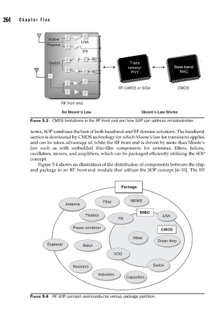
                       Figure 5.4 shows an illustration of the distribution of components between the chip
                    and package in an RF front-end module that utilizes the SOP concept [6–10]. The RF


                                                          Package

                                                  Filter      MEMS
                                   Antenna
                                                                  MMIC
                                           Fluidics                        LNA
                                                         PA
                                      Power combiner
                                                                           CMOS
                                                               Mixer
                                                                         Driver Amp
                           Duplexer       Balun
                                                       VCO

                                      Resistors                        Switch
                                                Inductors
                                                            Capacitors


                    FIGURE 5.4  RF SOP concept–semiconductor versus package partition.
   285   286   287   288   289   290   291   292   293   294   295