
Page 293 - System on Package_ Miniaturization of the Entire System
P. 293
Radio Fr equency System-on-Package (RF SOP) 267
5.4 RF SOP Technologies
SOP offers an ideal platform for miniaturization of RF front-end components better
than can be achieved in alternative technologies such as SOB, SIP, or SOC, as described
in Chapter 1. However, there are a multitude of challenges that need to be addressed to
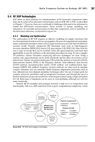
enable this SOP-based miniaturization. These include (1) design, modeling, and
simulation, (2) materials and processes for thin-film components, and (3) reliability of
the fabricated substrates, as depicted in Figure 5.6.
5.4.1 Modeling and Optimization
The optimization of RF SOP requires an effective modeling of complex structures that
involves mechanical motion and wave propagation. Because of computational constraints,
many commercial simulators utilize various approximations to provide fast and relatively
accurate results. Popular commercial EM simulation tools such as high-frequency
structure simulator (HFSS) [11], Sonnet [12], microstripes [13], IE3D [14], often limit the
size or type of circuits that can be modeled. Either the approximations used limit their
applicability to specific problems or the simulation time takes too long. To solve complex
3D problems, custom simulators employing full-wave techniques are used. Using a
custom code, approximations can be made selectively and the effect on accuracy can be
determined. Popular simulation techniques [15] include the method of moments (MoM),
finite-element method (FEM) in the frequency domain, finite-difference time-domain
(FDTD) method, transmission-line matrix (TLM) method, and multiresolution time-
domain (MRTD) [16] method. Frequency domain methods are often used to simulate
complex structures and can naturally handle frequency-dependent parameters such as
loss. Alternatively, time-domain simulation techniques allow the use of simple grids for
complex structures, parallelize well on inexpensive hardware, and through the use of a
Fourier transform can give the results for a wide frequency band using a single simulation
[15–16]. Both types of simulators can be used on most problems, although not with the
same complexity.
Modern RF 3D modules and packages demand a high level of compactness and
functionality. Full-wave EM numerical tools require computational complexity, which
Antennas
Modeling RFIDs
simulation
Passive components
• Capacitors • Inductors
Substrate technologies
Miniaturized • Resistors
• Ceramic • Organic Multifunction
• Glass • Silicon RF Systems Passive circuits
• Filters • Couplers
• Duplexers • Combiners
• Baluns • Dividers
Reliability
Switches
passive/
active
FIGURE 5.6 RF SOP technological challenges.