Page 298 - System on Package_ Miniaturization of the Entire System
P. 298

54
                                                        2
                                                  14
                                                  B  C D            E
                                                         M


                                           52
                                                             46
                                                                          4
                                                               RT/Duroid
                                z
                                                     3        8
                                 q            3   A      O               Ground plane
                                                                L   F
                                     x
                              y
                                                                Coaxial line
                                                                              Unit: mm
                                                           (a)
                                 5
                                                                    Simulated
                                                                    Measured
                                 4


                                VSWR  3


                                 2


                                 1
                                 0.5  1.0  1.5  2.0  2.5  3.0  3.5  4.0  4.5  5.0  5.5  6.0  6.5  7.0
                                                     Frequency (GHz)
                                                         (b)
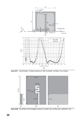
                    FIGURE 5.7  (a) Schematic of triband antenna on SOP substrate. (b) Return loss results.


                                               18 mm


                                                3.5 mm


                             25 mm     25 mm 1 mm


                                   9 mm       10 mm             9 mm


                              (a)               (b)                      (c)
                    FIGURE 5.8  The details of the designed antenna. (a) Side view. (b) Top view. (c) Bottom view.


               272
   293   294   295   296   297   298   299   300   301   302   303