Page 302 - System on Package_ Miniaturization of the Entire System
P. 302

276    Cha pte r  F i v e


                          0                                 0
                          5
                                                           10
                         10                                20
                        S 11  [dB]  15                    S 11  [dB]  30
                         20
                         25
                                                           40
                                               Measured                         Measured
                         30
                                               Simulated                        Simulated
                         35                                50
                           12 12.5 13 13.5 14 14.5 15   15.5 16  33 33.5 34 34.5 35 35.5 36 36.5 37
                                    Frequency [GHz]                   Frequency [GHz]
                                         (a)                               (b)
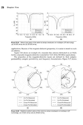
                    FIGURE 5.14  Return loss plots of the antenna arrays developed on multilayer LCP technology:
                    (a) 14-GHz array and (b) 35-GHz array.

                    applications. Because of the magneto-dielectric properties, it is easier to match to such
                    an antenna.
                       Figure 5.16 shows an example of a meander line antenna fabricated on an NiZn
                    ferrite composite (magneto-dielectric) material for VHF (30 to 300 MHz) applications.
                       The properties of the magneto-dielectric layers are defined by their complex
                    permeability, complex permittivity, and frequency characteristics. Figure 5.17 shows

                                                                           90
                                      90                          120               60
                             120              60
                                                                                       0
                                                 0                                   −5
                                                −5         150                      −10
                       150                    −10   30                             −15    30
                                             −15                                 −20
                                            −20                                 −25
                                          −25                                 −30
                                         −30                                 −35
                                        −35                                 −40
                     180               −40            0  180                                0


                       210                          330    210                            330


                             240              300                 240              300
                                     270                                  270

                                  Co-Pol Measured                       Co-Pol Measured
                                  Co-Pol Simulated                      Co-Pol Simulated
                                  Cross-Pol Measured                    Cross-Pol Measured
                                  Cross-Pol Simulated                   Cross-Pol Simulated
                                     (a)                                     (b)
                    FIGURE 5.15  Radiation pattern plots of the antenna arrays developed on multilayer LCP
                    technology: (a) 14-GHz array and (b) 35-GHz array.
   297   298   299   300   301   302   303   304   305   306   307