
Page 307 - System on Package_ Miniaturization of the Entire System
P. 307
Radio Fr equency System-on-Package (RF SOP) 281
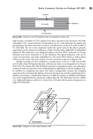
Inductor
Air cavity Dielectric
Ground plane
FIGURE 5.20 Inductor on an LTCC platform with an enclosed air cavity. [43]
high volume. A number of LTCC designs have been reported in the literature. One fully
embedded LTCC spiral inductor incorporating an air cavity between the spiral and
ground plane has been reported to achieve a quality factor of about 51 with an SRF of
9.1 GHz [44]. The air cavity employed under the spiral reduces the shunt parasitic
capacitance of the inductor resulting in a high Q factor and a high SRF of embedded
inductors. The inductors were designed using a low-loss LTCC dielectric of 114 μm
thickness and silver conductor of 12 μm thickness. The spiral inductors, with an air
cavity incorporated, were fully embedded in a five-layer LTCC block as well as those
without an air cavity. The cross section of such a structure is shown in Figure 5.20.
Another example of LTCC resulted in a quality factor of 93 at 1.1 GHz and an SRF
of 3.11 GHz when 3D helical inductors with circular turns were designed on 2a 0-layer
LTCC-951-AT ceramic [45]. The 3D helical inductors occupied less space. An inductance
of about 9.6 nH was reported. Such a helical inductor fabrication is shown in Figure 5.21.
In addition to occupying less space, the helical configuration reduces the coupling
capacitance by increasing the distance between the top turns and the underlying turns,
thereby preventing a considerable reduction in SRF. For higher Q, MEMS technologies
have been implemented by numerous authors [46–53]. The fabricated devices exhibit
very high performances such as Q values above 100 and self-resonance frequencies as
high as 50 GHz [46].
FIGURE 5.21 Diagram of a 3D helical inductor. [44]