
Page 309 - System on Package_ Miniaturization of the Entire System
P. 309
Radio Fr equency System-on-Package (RF SOP) 283
performance requirements. In addition, for many applications, the capacitance value
has to be stable within 0.3 percent over a 100°C range of temperature (TCC of <30 ppm/°C).
While the high Q and low TCC of capacitors in LTCC RF modules have been demonstrated
for decades [82–83], the dielectric mainly consists of ceramics and glass and requires
high-temperature crystallization, which is not congruous with low-temperature organic
substrate processing. LTCC technology is also limited by its high cost, incompatibility
with large-area processing, and low component density integration capability. Nevertheless,
LTCC technology for RF modules is still prevalent because of the low loss, good thermal
conductivity, and stability for high-frequency applications. The disadvantages of LTCC
technology can be overcome with LCP-based RF components [84]. Hence, there is an
increasing trend toward LCP-based RF circuits. However, the low dielectric constant of
this material makes the RF components and modules larger in size, which may limit the
component integration density; increases coupling between the components; and
degrades the total system performance. Furthermore, low-loss and low-TCC polymers
such as LCP and PTFE are not easily amenable to thin films, without compromising the
electrical properties.
Low-loss and high-Q capacitors have been achieved on a silicon platform using a
thin-film BCB buildup structure for RF wafer-level SOP functions [85]. High-K and low-
loss pyrochlore thin-film in organic substrate has also been explored [86]. This technology
enables complete RF integration for various applications such as matching networks,
filters, and even tunable components such as phase shifters. On the other hand, new
and novel compositions to achieve high Q and low TCC have been pursued using the
composite approach with ceramic fillers and low-loss, high-Q polymers. For example,
an LCP-based polymer composite has been engineered to replace LTCC components
such as capacitors.
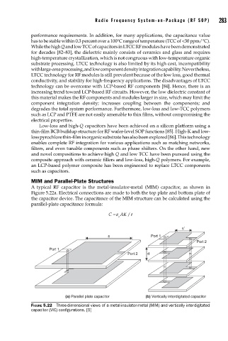
MIM and Parallel-Plate Structures
A typical RF capacitor is the metal-insulator-metal (MIM) capacitor, as shown in
Figure 5.22a. Electrical connections are made to both the top plate and bottom plate of
the capacitor device. The capacitance of the MIM structure can be calculated using the
parallel-plate capacitance formula:
C =ε AK t
/
o
s′
s Port 1
Port 2
Port 1
Port 2 d
(a) Parallel plate capacitor (b) Vertically interdigitated capacitor
FIGURE 5.22 Three-dimensional views of a metal-insulator-metal (MIM) and vertically interdigitated
capacitor (VIC) confi gurations. [5]