
Page 310 - System on Package_ Miniaturization of the Entire System
P. 310
284 Cha pte r F i v e
–12
where C is the capacitance (F), e is the permittivity of free space (8.854 × 10 F/m), A is
o
the area (m ), and t is the thickness (m). Insertion of a dielectric between the parallel
2
plates increases the capacitance by an amount proportional to the dielectric constant, K.
The dielectric constant is defined by K =εε/ , where e is the permittivity of the
o
dielectric. For large capacitors such as the RF ground capacitors, however, the electrode
size becomes too large for the MIM configuration to handle. The interdigital topology
tends to require a bigger area since the electric flux is generated laterally instead of
vertically such as in the MIM, which allows more electrode coverage.
An alternative capacitor implementation to the MIM topology [5] was proposed using
the vertically interdigitated configuration (VIC) shown in Figure 5.22b. The MIM structure
consisting of a dielectric layer sandwiched between two square plates of widths in
Figure 5.22a implements this type of capacitor, neglecting the higher-order excitation
mode. This capacitor can also be implemented by a parallel combination of pairs of plates
of smaller size. The plate size can be made smaller as more plates are deployed on many
dielectric layers. VIC topology occupies nearly an order of magnitude less area than the
MIM while maintaining comparable performance.
TCC Properties
The thermal coefficient of capacitance (TCC) is a very important parameter for RF
components [88]. Any deviation in component specifications with temperature can
adversely affect the frequency selection characteristics of the filter or resonator circuits
in RF modules. The TCC is becoming critical for various RF applications because of the
tighter design tolerances. The TCC values can be calculated from the measured
capacitance data with temperature using the following equation. This definition is used
in discrete capacitors and would also be applicable for embedded capacitors:
(C −C )
TCC = 85 C 25 C ×10 6
Δ T × C
25 C
where TCC = temperature coefficient of capacitance (ppm/°C), C 85°C = capacitance at
85°C, C 25°C = capacitance at 25°C, and ΔT = temperature difference between 85°C and
25°C = 60°C. The TCC can be positive or negative for both polymers and ceramics
depending on the material structure. BCB, for example, has a negative TCC behavior
over the temperature range of 25 to 125°C, showing its value of about –250 ppm/°C
[89]. Ferroelectrics have high-positive TCC, while most paraelectrics have negative
TCC. Similarly, polymers such as epoxy and polyimide show a positive TCC unlike
certain other polymers. The TCC tolerances for RF components are met by careful
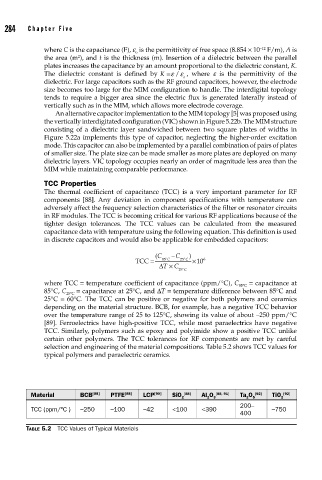
selection and engineering of the material compositions. Table 5.2 shows TCC values for
typical polymers and paraelectric ceramics.
Material BCB [88] PTFE [88] LCP [90] SiO 2 [88] Al O 3 [88, 91] Ta O 5 [92] TiO 2 [92]
2
2
200–
TCC (ppm/°C ) –250 –100 –42 <100 <390 –750
400
TABLE 5.2 TCC Values of Typical Materials