
Page 315 - System on Package_ Miniaturization of the Entire System
P. 315
Radio Fr equency System-on-Package (RF SOP) 289
R1 R2 R3 R4 R5 R6
(a)
60
50
Rs1-R4 (P1)
Rs1-R2 (P1)
Resistance (Ohm) 30 Rs2-R2 (P2)
40
Rs2-R4 (P2)
20
10
0
0 2 4 6 8 10 12 14 16
Frequency (GHz)
(b)
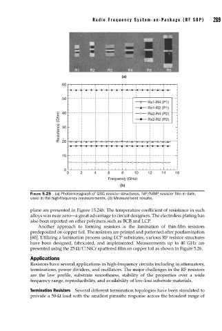
FIGURE 5.25 (a) Photomicrograph of GSG resistor structures, NiP/NiWP resistor fi lm in dark,
used in the high-frequency measurements. (b) Measurement results.
plane are presented in Figure 15.24b. The temperature coefficient of resistance in such
alloys was near zero—a great advantage to circuit designers. The electroless plating has
also been reported on other polymers such as BCB and LCP.
Another approach to forming resistors is the lamination of thin-film resistors
predeposited on copper foil. The resistors are printed and patterned after postlamination
[60]. Utilizing a lamination process using LCP substrates, various RF resistor structures
have been designed, fabricated, and implemented. Measurements up to 40 GHz are
presented using the 25 Ω/ NiCr sputtered film on copper foil as shown in Figure 5.26.
Applications
Resistors have several applications in high-frequency circuits including in attenuators,
terminations, power dividers, and oscillators. The major challenges in the RF resistors
are the low profile, substrate smoothness, stability of the properties over a wide
frequency range, reproducibility, and availability of low-loss substrate materials.
Termination Resistors Several different termination topologies have been simulated to
provide a 50-Ω load with the smallest parasitic response across the broadest range of