
Page 317 - System on Package_ Miniaturization of the Entire System
P. 317
Radio Fr equency System-on-Package (RF SOP) 291
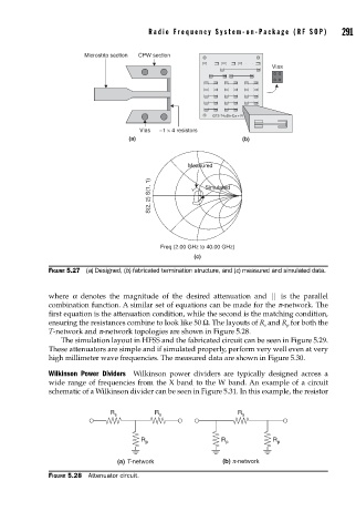
Microstrip section CPW section
Vias
GT2-T4uStr-Cu + R
Vias ~1 × 4 resistors
(a) (b)
Measured
S(2, 2) S(1, 1) Simulated
Freq (2.00 GHz to 40.00 GHz)
(c)
FIGURE 5.27 (a) Designed, (b) fabricated termination structure, and (c) measured and simulated data.
where a denotes the magnitude of the desired attenuation and || is the parallel
combination function. A similar set of equations can be made for the p-network. The
first equation is the attenuation condition, while the second is the matching condition,
ensuring the resistances combine to look like 50 Ω. The layouts of R and R for both the
s
p
T-network and p-network topologies are shown in Figure 5.28.
The simulation layout in HFSS and the fabricated circuit can be seen in Figure 5.29.
These attenuators are simple and if simulated properly, perform very well even at very
high millimeter wave frequencies. The measured data are shown in Figure 5.30.
Wilkinson Power Dividers Wilkinson power dividers are typically designed across a
wide range of frequencies from the X band to the W band. An example of a circuit
schematic of a Wilkinson divider can be seen in Figure 5.31. In this example, the resistor
R s R s R s
R p R p R p
(a) T-network (b) p-network
FIGURE 5.28 Attenuator circuit.