
Page 316 - System on Package_ Miniaturization of the Entire System
P. 316
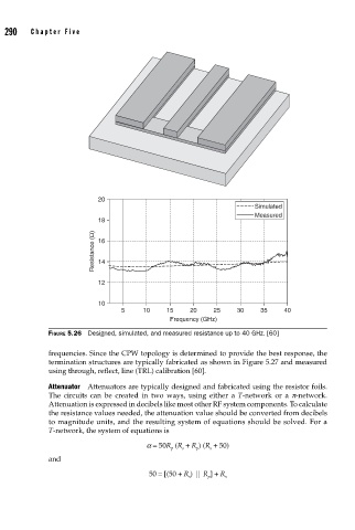
290    Cha pte r  F i v e


                                 20
                                                                          Simulated
                                                                          Measured
                                 18
                                Resistance (Ω)  16


                                 14

                                 12

                                 10
                                       5     10    15    20    25    30    35     40
                                                    Frequency (GHz)
                    FIGURE 5.26  Designed, simulated, and measured resistance up to 40 GHz. [60]

                    frequencies. Since the CPW topology is determined to provide the best response, the
                    termination structures are typically fabricated as shown in Figure 5.27 and measured
                    using through, reflect, line (TRL) calibration [60].

                    Attenuator  Attenuators are typically designed and fabricated using the resistor foils.
                    The circuits can be created in two ways, using either a  T-network or a  p-network.
                    Attenuation is expressed in decibels like most other RF system components. To calculate
                    the resistance values needed, the attenuation value should be converted from decibels
                    to magnitude units, and the resulting system of equations should be solved. For a
                    T-network, the system of equations is
                                              a = 50R  (R + R ) (R + 50)
                                                           p
                                                              s
                                                    p
                                                       s
                    and
                                              50 = [(50 + R ) || R ] + R s
                                                         s
                                                              p