
Page 300 - System on Package_ Miniaturization of the Entire System
P. 300
274 C h a p t er Fiv e
0° 0°
−30° 30° −30° 30°
−60° 60° −60° 60°
−90° 90° −90° 90°
−8 −25
−120° −4 120° −120° −15 120°
0 −5
−150° 150° −150° 150°
180° 180°
Phi = 0 Theta = 90
Phi = 90
FIGURE 5.11 Simulated far-fi eld pattern of the antenna at 6 GHz.
omnidirectional pattern like that of a dipole, and the simulated peak gain of the antenna
is 2.5 dBi at a resonant frequency of 6 GHz.
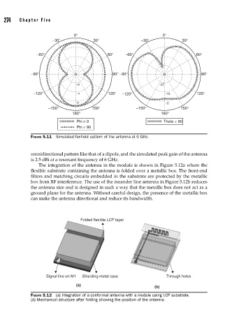
The integration of the antenna in the module is shown in Figure 5.12a where the
flexible substrate containing the antenna is folded over a metallic box. The front-end
filters and matching circuits embedded in the substrate are protected by the metallic
box from RF interference. The use of the meander line antenna in Figure 5.12b reduces
the antenna size and is designed in such a way that the metallic box does not act as a
ground plane for the antenna. Without careful design, the presence of the metallic box
can make the antenna directional and reduce its bandwidth.
Folded flexible LCP layer
Signal line on M1 Shielding metal case Through holes
(a)
(b)
FIGURE 5.12 (a) Integration of a conformal antenna with a module using LCP substrate.
(b) Mechanical structure after folding showing the position of the antenna.