
Page 335 - System on Package_ Miniaturization of the Entire System
P. 335
Radio Fr equency System-on-Package (RF SOP) 309
Planer
antenna
Multi-layer
filter
MMIC +
embedded
passives
(a) (b)
−15 3
−18 2
IF power (dBm) −21 1 0 Gain (dB)
−24
−27 −1
−30 −2
5 5.2 5.4 5.6 5.8 6
RF frequency (GHz)
(c)
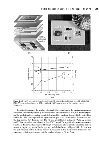
FIGURE 5.44 (a) A schematic view of a multilayer RF front-end architecture. (b) A 3D integrated
LTCC RF front-end module for a 802.11a WLAN. (c) Measured gain of the receiver versus
frequency.
To utilize the space of the module effectively, the geometries of the passive components
have been chosen very carefully. A cavity backed patch antenna (CBPA) has been designed
for the module. A three-section coupled stripline filter has been designed to be embedded
inside the LTCC package with its input and output ports connected to the antenna and
the duplexer switch through vias. The RF functional blocks, including PA, LNA, mixers,
and VCO are attached on the bottom of the LTCC board. The specifications of the functional
blocks are determined and verified through system simulations based on the IEEE 802.11a
standard. A photograph of the integrated module is shown in Figure 5.44b. To evaluate
the performance of the module, each of the sections in the module was fabricated and
measured with the performance of the receiver shown in Figure 5.44c.