
Page 332 - System on Package_ Miniaturization of the Entire System
P. 332
306 Cha pte r F i v e
and higher data transfer rate. Two major challenges exist in today’s RFID technology
advances toward the practical level. One is the design of tag antennas with higher
efficiency and better impedance matching for IC chips with high capacitive reactance.
This is essential to maximize the RFID system performance. Another major challenge is
the realization of ultra-low-cost RFID tags. Economical applications require the cost of
individual tags to drop down to one or two cents. Three types of antennas specifically
designed to enhance RFID performance (as compared to the antennas described earlier
which were for WiFi applications) are described below [77–78].
Meander Line
An RFID antenna is usually built to achieve half-wavelength resonance at first for
efficiency optimization. This is approximately equal to the maximum length, when the
dipole antenna is stretched from one end to the other. In the UHF band, a half-wave
dipole antenna is almost 16 cm in free space. For the purpose of reducing tag sizes, the
meander line structure is an attractive choice. The arc-shaped configuration is a
modification of the meander line. It exhibits a smoother transition along the radiating
arms. This class of antenna provides the largest size reduction (down to a quarter
wavelength) at the desired frequency at the expense of a slight decrease in gain (usually
5 percent lower) due to a less effective radiating length.
Dual Polarization Structure
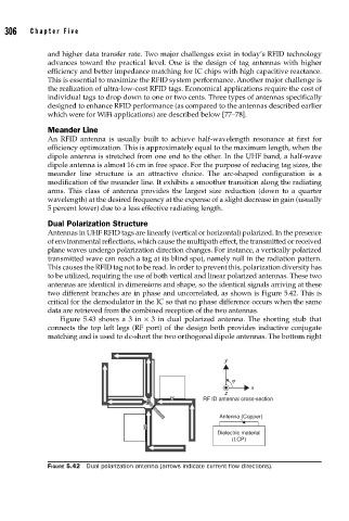
Antennas in UHF RFID tags are linearly (vertical or horizontal) polarized. In the presence
of environmental reflections, which cause the multipath effect, the transmitted or received
plane waves undergo polarization direction changes. For instance, a vertically polarized
transmitted wave can reach a tag at its blind spot, namely null in the radiation pattern.
This causes the RFID tag not to be read. In order to prevent this, polarization diversity has
to be utilized, requiring the use of both vertical and linear polarized antennas. These two
antennas are identical in dimensions and shape, so the identical signals arriving at these
two different branches are in phase and uncorrelated, as shown is Figure 5.42. This is
critical for the demodulator in the IC so that no phase difference occurs when the same
data are retrieved from the combined reception of the two antennas.
Figure 5.43 shows a 3 in × 3 in dual polarized antenna. The shorting stub that
connects the top left legs (RF port) of the design both provides inductive conjugate
matching and is used to dc-short the two orthogonal dipole antennas. The bottom right
y
j
x
z
G RF ID antennal cross-section
2
1
Antenna (Copper)
G
Dielectric material
(LCP)
FIGURE 5.42 Dual polarization antenna (arrows indicate current fl ow directions).