
Page 85 - Introduction to Transfer Phenomena in PEM Fuel Cells
P. 85
74 Introduction to Transfer Phenomena in PEM Fuel Cells
2.5.2. Ohmic polarization
With increasing fuel flow rate, the current density increases but the
internal resistance of the electrolyte causes a decrease in the voltage at the
electrodes. There is a voltage decrease (η ohm), also called ohmic losses,
which is mainly a function of the electrical resistance of the membrane.
These losses are due to conjugated phenomena, which include the electrical
resistance of the electrode, the contact resistances and the resistance of the
electrolyte to the passage of ions. The latter is characterized by the ionic
+
conductivity (H ) expressed by equation [3.84].
This resistance is actually dominant compared to the electrical resistance
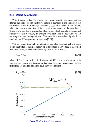
of the electrodes; it depends mainly on temperature. The voltage loss, caused
by ohmic losses, is simply expressed by Ohm’s law [SPI 07]:
η ohm = R ⋅ j [2.74]
m
where (R m) is the Area Specific Resistance (ASR) of the membrane and it is
expressed in (Ω.cm²). It depends on the ionic (protonic) conductivity of the
+
membrane (H ) and its thickness (e m) expressed in (cm):
e
R = m [2.75]
m
σ +
H
Figure 2.5. Evolution of ohmic losses