
Page 34 - Introduction to chemical reaction engineering and kinetics
P. 34
16 Chapter 1: Introduction
mechanical design of equipment (see Chapter 11 for elaboration of these terms). Other
aspects are implicit, but are not treated explicitly: instrumentation and process control,
economic, and socioeconomic (environmental and safe-operation). Reactor design is a
term we may apply to a new installation or modification; otherwise, we may speak of
the analysis of performance of an existing reactor.
1.5.2 Parameters Affecting Reactor Performance
The term “reactor performance” usually refers to the operating results achieved by a re-
actor, particularly with respect to fraction of reactant converted or product distribution
for a given size and configuration; alternatively, it may refer to size and configuration
for a given conversion or distribution. In any case, it depends on two main types of be-
havior: (1) rates of processes involved, including reaction and heat and mass transfer,
sometimes influenced by equilibrium limitations; and (2) motion and relative-motion
of elements of fluid (both single-phase and multiphase situations) and solid particles
(where involved), whether in a flow system or not.
At this stage, type (1) is more apparent than type (2) and we provide some prelimi-
nary discussion of (2) here. Flow characteristics include relative times taken by elements
of fluid to pass through the reactor (residence-time distribution), and mixing character-
istics for elements of fluid of different ages: point(s) in the reactor at which mixing takes
place, and the level of segregation at which it takes place (as a molecular dispersion or
on a macroscopic scale). Lack of sufficient information on one or both of these types is
a major impediment to a completely rational reactor design.
1.5.3 Balance Equations
One of the most useful tools for design and analysis of performance is the balance equa-
tion. This type of equation is used to account for a conserved quantity, such as mass or
energy, as changes occur in a specified system; element balances and stoichiometry, as
discussed in Section 1.4.4, constitute one form of FUSS balance.
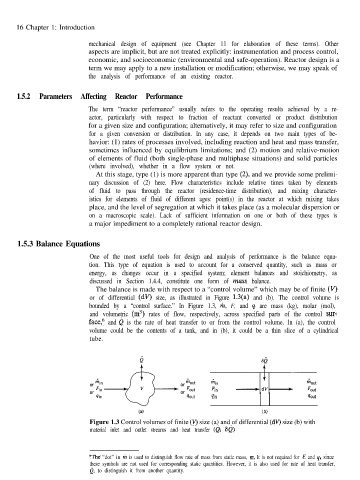
The balance is made with respect to a “control volume” which may be of finite (V)
or of differential (dV) size, as illustrated in Figure 1.3(a) and (b). The control volume is
bounded by a “control surface.” In Figure 1.3, rit, F, and 4 are mass (kg), molar (mol),
and volumetric (m3) rates of flow, respectively, across specified parts of the control sur-
face,‘j and f! is the rate of heat transfer to or from the control volume. In (a), the control
volume could be the contents of a tank, and in (b), it could be a thin slice of a cylindrical
tube.
4in
(a) (b)
Figure 1.3 Control volumes of finite (V) size (a) and of differential (dV) size (b) with
material inlet and outlet streams and heat transfer (b, Sb)
@Ike “dot” in riz is used to distinguish flow rate of mass from static mass, m. It is not required for F and q, since
these symbols are not used for corresponding static quantities. However, it is also used for rate of heat transfer,
d, to distinguish it from another quantity.