
Page 73 - Introduction to chemical reaction engineering and kinetics
P. 73
3.4 Experimental Strategies for Determining Rate Parameters 55
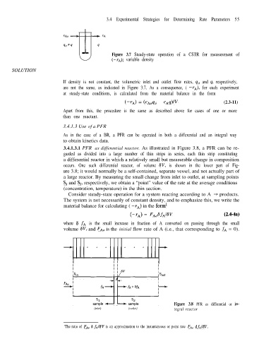
Figure 3.7 Steady-state operation of a CSTR for measurement of
(-IA); variable density
SOLUTION
If density is not constant, the volumetric inlet and outlet flow rates, q0 and q. respectively,
are not the same, as indicated in Figure 3.7. As a consequence, ( -rA), for each experiment
at steady-state conditions, is calculated from the material balance in the form
(2.3-11)
(-rA) = (CA& - cAq)/v
Apart from this, the procedure is the same as described above for cases of one or more
than one reactant.
3.4.1.3 Use of a PFR
As in the case of a BR, a PFR can be operated in both a differential and an integral way
to obtain kinetics data.
3.4.1.3.1 PFR as differential reactor. As illustrated in Figure 3.8, a PFR can be re-
garded as divided into a large number of thin strips in series, each thin strip constituting
a differential reactor in which a relatively small but measurable change in composition
occurs. One such differential reactor, of volume SV, is shown in the lower part of Fig-
ure 3.8; it would normally be a self-contained, separate vessel, and not actually part of
a large reactor. By measuring the small change from inlet to outlet, at sampling points
S, and S,, respectively, we obtain a “point” value of the rate at the average conditions
(concentration, temperature) in the thin section.
Consider steady-state operation for a system reacting according to A -+ products.
The system is not necessarily of constant density, and to emphasize this, we write the
material balance for calculating ( -rA) in the form1
(-rA) = FAoSfA18V (2.4-4a)
where 6 fA is the small increase in fraction of A converted on passing through the small
volume 6V, and FAo is the initial flow rate of A (i.e., that corresponding to fA = 0).
Figure 3.8 PFR as differential or in-
(inlet) (outlet) tegral reactor
‘The ratio of FA, 6 fA18V is an approximation to the instantaneous or point rate FAN dfAldV.