
Page 302 - Laboratory Manual in Physical Geology
P. 302
Unconformities Cardboard Models
Structural geologists must locate, observe, and interpret Six cardboard block diagrams (Cardboard Models 1–6)
many different structures. Fundamentally, these include are provided at the back of this laboratory manual.
unconformities, faults, and folds. There are three common Unlike illustrated block diagrams, these actually are
types of unconformities (see FIGURE 8.1 , p. 209): three-dimensional models that you can analyze from
any perspective. To analyze and interpret the cardboard
■ Disconformity —an unconformity between relatively
parallel strata. models, you will need to understand and apply symbols
for geologic structures ( FIGURE 10.5 ) and follow the set of
■ Angular unconformity —an unconformity between simple rules for interpreting geologic maps on the tops of
nonparallel strata. the models ( FIGURE 10.9 ).
■ Nonconformity —an unconformity between
sedimentary rock/sediment and non-sedimentary
(igneous or metamorphic) rock beneath or beside it.
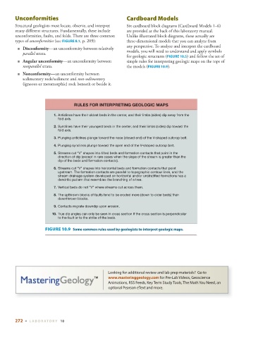
RULES FOR INTERPRETING GEOLOGIC MAPS
1. Anticlines have their oldest beds in the center, and their limbs (sides) dip away from the
fold axis.
2. Synclines have their youngest beds in the center, and their limbs (sides) dip toward the
fold axis.
3. Plunging anticlines plunge toward the nose (closed end) of the V-shaped outcrop belt.
4. Plunging synclines plunge toward the open end of the V-shaped outcrop belt.
5. Streams cut “V” shapes into tilted beds and formation contacts that point in the
direction of dip (except in rare cases when the slope of the stream is greater than the
dip of the beds and formation contacts).
6. Streams cut “V” shapes into horizontal beds and formation contacts that point
upstream. The formation contacts are parallel to topographic contour lines, and the
stream drainage system developed on horizontal and/or unstratified formations has a
dendritic pattern that resembles the branching of a tree.
7. Vertical beds do not “V” where streams cut across them.
8. The upthrown blocks of faults tend to be eroded more (down to older beds) than
downthrown blocks.
9. Contacts migrate downdip upon erosion.
10. True dip angles can only be seen in cross section if the cross section is perpendicular
to the fault or to the strike of the beds.
FIGURE 10.9 Some common rules used by geologists to interpret geologic maps.
Looking for additional review and lab prep materials? Go to
www.masteringgeology.com for Pre-Lab Videos, Geoscience
Animations, RSS Feeds, Key Term Study Tools, The Math You Need, an
optional Pearson eText and more.
272 ■ L ABOR ATORY 10