
Page 400 - Lindens Handbook of Batteries
P. 400
LiTHiUM PriMAry BATTerieS 14.65
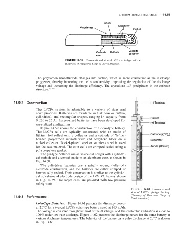
FIGURE 14.59 Cross-sectional view of Li/CFx coin-type battery.
(Courtesy of Panasonic Corp. of North America.)
The polycarbon monofluoride changes into carbon, which is more conductive as the discharge
progresses, thereby increasing the cell’s conductivity, improving the regulation of the discharge
voltage and increasing the discharge efficiency. The crystalline LiF precipitates in the cathode
structure. 1,43,44
14.9.2 Construction
The Li/CFx system is adaptable to a variety of sizes and
configurations. Batteries are available in flat coin or button,
cylindrical, and rectangular shapes, ranging in capacity from
0.020 to 25 Ah; larger-sized batteries have been developed for
specialized applications.
Figure 14.59 shows the construction of a coin-type battery.
The Li/CFx cells are typically constructed with an anode of
lithium foil rolled onto a collector and a cathode of Teflon-
bonded polycarbon monofluoride and acetylene black on a
nickel collector. Nickel-plated steel or stainless steel is used
for the case material. The coin cells are crimped-sealed using a
polypropylene gasket.
The pin-type batteries use an inside-out design with a cylindri-
cal cathode and a central anode in an aluminum case, as shown in
Fig. 14.60.
The cylindrical batteries use a spirally wound (jelly-roll)
electrode construction, and the batteries are either crimped or
hermetically sealed. Their construction is similar to the cylindri-
cal spiral-wound electrode design of the Li/MnO battery shown
2
in Fig. 14.39. The larger cells are provided with low-pressure
safety vents.
FIGURE 14.60 Cross-sectional
view of Li/CFx pin-type battery.
14.9.3 Performance (Courtesy of Panasonic Corp. of
North America.)
Coin-Type Batteries. Figure 14.61 presents the discharge curves
at 20°C for a typical Li/CFx coin-type battery rated at 165 mAh.
The voltage is constant throughout most of the discharge, and the coulombic utilization is close to
100% under low-rate discharge. Figure 14.62 presents the discharge curves for the same battery at
various discharge temperatures. The behavior of the battery on a pulse discharge at 20°C is shown
in Fig. 14.63.