
Page 55 - Lindens Handbook of Batteries
P. 55
2.12 PRINCIPLES OF OPERATION –
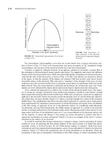
Interfacial surface tension γ, dynes/cm Electrode – Electrolyte
Electrocapillary
–
maximum (ecm)
+
Potential, V (vs. H /H electrode) FIGURE 2.10 Orientation of
2
water molecules in the electrical
FIGURE 2.9 Generalized representation of an electro- double layer at a negatively charged
capillary curve. electrode.
The characteristic electrocapillary curve that one would obtain from a typical electrolyte solu-
tion is shown in Fig. 2.9. From such measurements and, more accurately, by AC im pedance bridge
measurements, the structure of the electrical double layer has been determined. 5
Consider a negatively charged electrode in an aqueous solution of electrolyte. Assume that at
this potential no electrochemical charge transfer takes place. For simplicity and clarity, the different
features of the electrical double layer will be described individually. Orientation of solvent molecules,
water for the sake of this discussion, is shown in Fig. 2.10. The water dipoles are oriented as shown
in the figure, so that the majority of the dipoles are oriented with their positive ends (arrow heads)
toward the surface of the electrode. This represents a “snapshot” of the structure of the layer of water
molecules since the electrical double layer is a dynamic system that is in equilibrium with water in the
bulk solution. Since the representation is statistical, not all dipoles are oriented the same way. Some
dipoles are more influenced by dipole-dipole interactions than by dipole-electrode interactions.
Next, consider the approach of a cation to the vicinity of the electrical double layer. The major-
ity of cations are strongly solvated by water dipoles and maintain a sheath of water dipoles around
them despite the orienting effect of the double layer. With a few exceptions, cations do not approach
right up to the electrode surface but remain outside the primary layer of solvent molecules and usu-
ally retain their solvation sheaths. Figure 2.11 shows a typical example of a cation in the electrical
double layer. The establishment that this is the most likely approach of a typical cation comes partly
from experimental AC impedance measurements of mixed electrolytes and mainly from calculations
of the free energy of approach of an ion to the electrode surface. In considering water-electrode,
ion-electrode, and ion-water interactions, the Gibbs energy of approach of a cation to an electrode
surface is strongly influenced by the hydration of the cation. The general result is that cations of very
+
large radius (and thus of low hydration) such as Cs can contact/adsorb on the electrode surface, but
for the majority of cations the change in free energy on contact absorption is positive and thus is
+
6
against the mechanism of contact adsorption. Figure 2.12 gives an example of the ion Cs contact-
adsorbed on the surface of an electrode.
It would be expected that because anions have a negative charge, contact adsorption of anions
would not occur. In analyzing the free-energy balance of the anion system, it is found that anion-
electrode contact is favored because the net Gibbs-energy balance is negative. Both from these
calculations and from experimental measurements, anion contact adsorption is found to be relatively
common. Figure 2.13 shows the generalized case of anion adsorption on an electrode. There are
exceptions to this type of adsorption. Calculation of the Gibbs energy of contact adsorption of the