
Page 126 - Lindens Handbook of Batteries
P. 126
BATTERY DESIGN 5.3
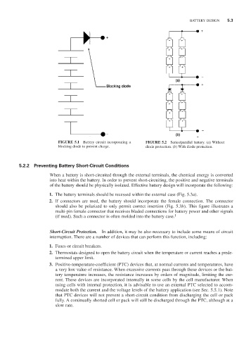
FIGURE 5.1 Battery circuit incorporating a FIGURE 5.2 Series/parallel battery. (a) Without
blocking diode to prevent charge. diode protection. (b) With diode protection.
5.2.2 Preventing Battery Short-Circuit Conditions
When a battery is short-circuited through the external terminals, the chemical energy is converted
into heat within the battery. In order to prevent short-circuiting, the positive and negative terminals
of the battery should be physically isolated. Effective battery design will incorporate the following:
1. The battery terminals should be recessed within the external case (Fig. 5.3a).
2. If connectors are used, the battery should incorporate the female connection. The connector
should also be polarized to only permit correct insertion (Fig. 5.3b). This figure illustrates a
multi-pin female connector that receives bladed connections for battery power and other signals
1
(if used). Such a connector is often molded into the battery case.
Short-Circuit Protection. In addition, it may be also necessary to include some means of circuit
interruption. There are a number of devices that can perform this function, including:
1. Fuses or circuit breakers.
2. Thermostats designed to open the battery circuit when the temperature or current reaches a prede-
termined upper limit.
3. Positive-temperature-coefficient (PTC) devices that, at normal currents and temperatures, have
a very low value of resistance. When excessive currents pass through these devices or the bat-
tery temperature increases, the resistance increases by orders of magnitude, limiting the cur-
rent. These devices are incorporated internally in some cells by the cell manufacturer. When
using cells with internal protection, it is advisable to use an external PTC selected to accom-
modate both the current and the voltage levels of the battery application (see Sec. 5.5.1). Note
that PTC devices will not prevent a short-circuit condition from discharging the cell or pack
fully. A continually shorted cell or pack will still be discharged through the PTC, although at a
slow rate.