
Page 128 - Lindens Handbook of Batteries
P. 128
BATTERY DESIGN 5.5
Discharge beyond the cell manufacturer’s recommended operating range is not suggested, so
precautions should be taken at the system level if such discharge is possible. If external conditions
are likely to cause discharge below recommended limits, then protection within the battery pack may
be required. This is often utilized in lithium rechargeable chemistries.
Some cells are designed to withstand a forced discharge to specified discharge currents. The cells
may also be designed with internal protection, such as fuses or thermal cutoff devices, to interrupt
the discharge if an unsafe condition develops.
This condition of cell unbalance could be exacerbated with rechargeable cells, as the individual cell
capacities could change during cycling. To minimize this effect, rechargeable batteries should at least
be constructed with “matched” cells, that is, cells having nearly identical capacities. Cells are sorted,
within grades, by at least one cycle of charge and discharge. Typically cells are considered matched
when the capacity range is within 3%. Recent advances in manufacturing control have reduced the
number of cell grades. Some manufacturers have reached the optimal goal of one grade, which negates
the need of matching. This information is readily available from the battery companies.
Cell imbalance, however, can occur after the cells are assembled into a battery pack and utilized
in the end application. Such cell imbalance can result from uneven thermal gradients across the bat-
tery that cause some cells to reach higher temperatures than others. This temperature gradient will
cause a difference in cell self-discharge, potentially leading to cell imbalance. If imbalance occurs
within the battery pack, then corrective action must be taken to prevent an accumulation of imbal-
ance. Some chemistries permit a low-rate overcharge to correct imbalance, while other chemistries,
such as lithium-ion/polymer, require rebalancing by electronic methods.
Battery Design to Prevent Voltage Reversal. Even though matched cells are used, other battery
designs or applications can cause an imbalance in cell capacity. One example is the use of voltage taps
on cells of a multicell battery in a series string. In this design, the cells are not discharged equally.
Many early battery designs using Leclanché-type cells incorporated the use of voltage taps.
Batteries with as many as 30 cells in series (45 V) were common, with taps typically at 3, 9, 13.5 V,
and so on. When the cells with the lower voltage taps were discharged, they could leak. This leakage
could cause corrosion, but usually these cells would not be prone to rupture. With the advent of the
high-energy, tightly sealed cells, this is no longer the case. Cells driven into voltage reversal may
rupture or explode. In order to avoid problems, the battery should be designed with electrically inde-
pendent sections for each voltage output. If possible, the device should be designed to be powered by
a single input voltage source. DC to DC converters can be used to safely provide for multiple voltage
outputs. Converters are now available with efficiencies greater than 90%.
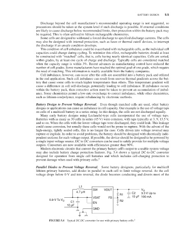
Modern electronic circuits that convert the primary battery cell’s output to a usable system voltage
may also include battery charge protection features. Fig. 5.4 shows a typical DC-to-DC converter
designed for operation from single cell batteries and which includes cell-charging protection to
prevent damage when used with primary cells. 3
Parallel Diodes to Prevent Voltage Reversal. Some battery designers, particularly for multicell
lithium primary batteries, add diodes in parallel to each cell to limit voltage reversal. As the cell
voltage drops below 0 V and into reversal, the diode becomes conducting and diverts most of the
L1
SW VOUT V O
4.7 µH C2 3.3 V Up to
R1
VBAT FB 10 µF 100 mA
0.9-V To V O R2
C1 EN
10 µF
GND
FIGURE 5.4 Typical DC:DC converter for use with primary battery cells. 2