
Page 130 - Lindens Handbook of Batteries
P. 130
BATTERY DESIGN 5.7
Permanent Overcurrent
thermal fuse or PTC
TCO
fuse
V out +
Blocking
diodes
Complete
discharge
switch 3V 3V
3V 3V
Discharge
resistor
3V 3V
V out –
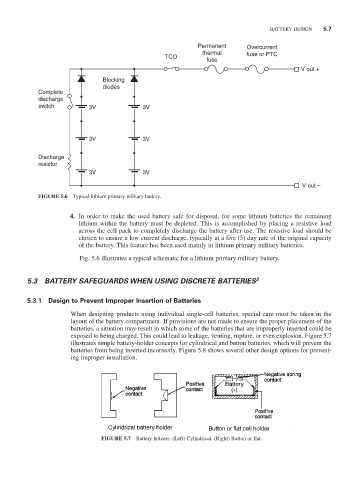
FIGURE 5.6 Typical lithium primary military battery.
4. In order to make the used battery safe for disposal, for some lithium batteries the remaining
lithium within the battery must be depleted. This is accomplished by placing a resistive load
across the cell pack to completely discharge the battery after use. The resistive load should be
chosen to ensure a low current discharge, typically at a five (5) day rate of the original capacity
of the battery. This feature has been used mainly in lithium primary military batteries.
Fig. 5.6 illustrates a typical schematic for a lithium primary military battery.
5.3 BATTERY SAFEGUARDS WHEN USING DISCRETE BATTERIES 3
5.3.1 Design to Prevent Improper Insertion of Batteries
When designing products using individual single-cell batteries, special care must be taken in the
layout of the battery compartment. If provisions are not made to ensure the proper placement of the
batteries, a situation may result in which some of the batteries that are improperly inserted could be
exposed to being charged. This could lead to leakage, venting, rupture, or even explosion. Figure 5.7
illustrates simple battery-holder concepts for cylindrical and button batteries, which will prevent the
batteries from being inserted incorrectly. Figure 5.8 shows several other design options for prevent-
ing improper installation.
FIGURE 5.7 Battery holders. (Left) Cylindrical. (Right) Button or flat.