
Page 113 - Low Temperature Energy Systems with Applications of Renewable Energy
P. 113
102 Low-Temperature Energy Systems with Applications of Renewable Energy
Fig. 3.16 Block diagram of inflow and exhaust ventilation with a plate-type heat exchanger.
1, frame; 2, partition; 3, heat exchanger; 4, intake fan; 5, exhaust fan; 6, condensate drain;
7, 8, filters.
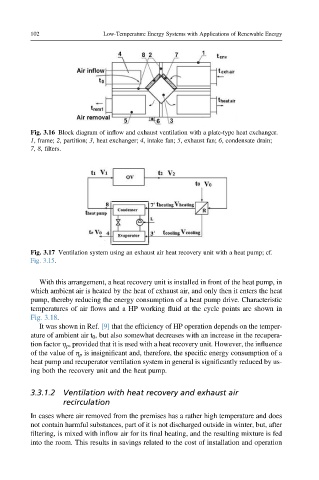
Fig. 3.17 Ventilation system using an exhaust air heat recovery unit with a heat pump; cf.
Fig. 3.15.
With this arrangement, a heat recovery unit is installed in front of the heat pump, in
which ambient air is heated by the heat of exhaust air, and only then it enters the heat
pump, thereby reducing the energy consumption of a heat pump drive. Characteristic
temperatures of air flows and a HP working fluid at the cycle points are shown in
Fig. 3.18.
It was shown in Ref. [9] that the efficiency of HP operation depends on the temper-
ature of ambient air t 0 , but also somewhat decreases with an increase in the recupera-
tion factor h p , provided that it is used with a heat recovery unit. However, the influence
of the value of h p is insignificant and, therefore, the specific energy consumption of a
heat pump and recuperator ventilation system in general is significantly reduced by us-
ing both the recovery unit and the heat pump.
3.3.1.2 Ventilation with heat recovery and exhaust air
recirculation
In cases where air removed from the premises has a rather high temperature and does
not contain harmful substances, part of it is not discharged outside in winter, but, after
filtering, is mixed with inflow air for its final heating, and the resulting mixture is fed
into the room. This results in savings related to the cost of installation and operation