
Page 179 - Low Temperature Energy Systems with Applications of Renewable Energy
P. 179
[55]
B
Case
A
Case
33 25 Dt ev 0.1 0.154 TS-diagram 30 30 Dt cond e t c.w.outlet 1.2 0.858 TS-diagram 124 90 Dt gen 462 0.225; 180 0.30; 25 25 Dt ab e t input.app. 0 0.315; 210 0.39; 8.62 11.2 ¼ G 15 =G 2 ¼ x w:s: Þ x w:s: Þ=ðx s:s: 1660 40; 1350 40; 1 ¼ x 2 þ D r:c: ; t c:w:outlet 1:2MPa
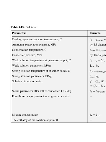
Formula t b.outlet ¼ t 0 by ¼ t cond by e t s ¼ t 9 h 9 x w.s. ; ¼ t 13 h 13 x s.s. ; G s:s: =D ¼ f ¼ðx 2 ¼ t 2 e x 13 ¼ x 8 e
C C kJ/kg
output, outlet, C; outlet:
C generator 8
temperature, MPa pressure, C generator at kJ/kg absorber at kJ/kg condenser, reflux at point at
Solution. evaporation evaporation temperature, MPa pressure, temperature parameters, temperature parameters, ratios circulation after parameters parameters vapor concentration solution the of
4.E2 Parameters agent Condensation Condenser solution solution solution solution Equilibrium enthalpy
Table Cooling Ammonia Weak Weak Strong Strong Solution Steam Mixture The