
Page 182 - Low Temperature Energy Systems with Applications of Renewable Energy
P. 182
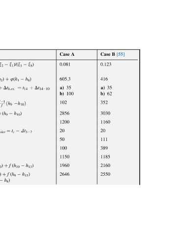
[55]
                     B            35  62
                     Case  0.123  416  a)  b)  352  3030  1160  20  111  389  1185  2160  2550


                     A            35  100
                     Case  0.081  605.3  a)  b)  102  2856  1200  20  50  100  1150  1960  2646


                                  þ Dt 14 10


                         x 8 )  h 8 )                         h 13 )
                                  t 14           Dt 3 7          h 15 )
                         x 1 )/(x 1  4(h 1  ¼   h 10 Þ  h 10 )        t c  (h 10     (h 9


                               þ  h 2 )  þ Dt h:ex:  þ f  1 ðh 9  f  (h 9  ¼  f  þ  f  þ  h 8 )
                         G 8 /G 2 ¼(x 2     (h 1  t 14  ¼  h 14  1)     (f  h 3     Dt cooler     h 6     q c     h 4     h 10 )     h 9 )     4(h 1

                     Formula  ¼  4  ¼  q r.c.  t 10  a)  h 10  b)  ¼  h 15  ¼  q h.ex  h 2  ¼  q c  t 3  ¼  t 7  h 7  ¼  q c  h 3  ¼  h 4  h 6  ¼  q 0  (h 7  ¼  q a  (h 1  ¼  q g  þ


                         (reflux   kJ/kg

                         condenser  C;  kJ/kg    C


                         reflux  kJ/kg  exchanger,  inlet,  kJ/kg  cooler,  after  kJ/kg

                         from  condenser,  heat  after  generator  exchanger,  kJ/kg condenser,  temperature  kJ/kg  plant,  of  kJ/kg  kJ/kg
                  Solution.dcont’d  reflux  of  reflux  of  load  parameters  at enthalpy  heat  of  load  of  load  vapor  cooler,  of  load  enthalpy  capacity  absorption,  on  of,  load


                  4.E2  Parameters  withdrawal  ratio)  heat  solution  solution  heat  heat  agent  heat  inlet  cooling  released  heat Generator
                  Table  Specific  Specific  Weak  Strong  Specific  Specific  Cooling  Specific  Throttle  Specific  Heat