
Page 230 - Low Temperature Energy Systems with Applications of Renewable Energy
P. 230
Heating with geothermal systems 217
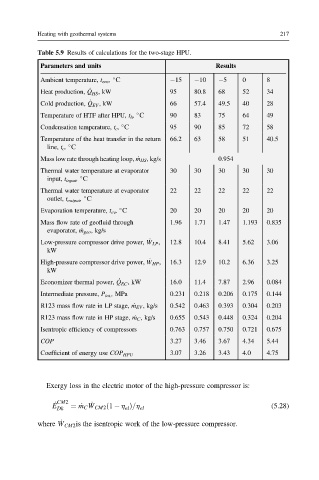
Table 5.9 Results of calculations for the two-stage HPU.
Parameters and units Results
Ambient temperature, t env , S 15 10 5 0 8
_
Heat production, Q HS , kW 95 80.8 68 52 34
_
Cold production, Q EV , kW 66 57.4 49.5 40 28
Temperature of HTF after HPU, t h , S 90 83 75 64 49
Condensation temperature, t c , S 95 90 85 72 58
Temperature of the heat transfer in the return 66.2 63 58 51 40.5
line, t c , S
Mass low rate through heating loop, _ m HS , kg/s 0.954
Thermal water temperature at evaporator 30 30 30 30 30
input, t input , S
Thermal water temperature at evaporator 22 22 22 22 22
outlet, t output , S
Evaporation temperature, t ev , S 20 20 20 20 20
Mass flow rate of geofluid through 1.96 1.71 1.47 1.193 0.835
evaporator, _ m geo , kg/s
Low-pressure compressor drive power, _ W LP , 12.8 10.4 8.41 5.62 3.06
kW
High-pressure compressor drive power, _ W HP , 16.3 12.9 10.2 6.36 3.25
kW
Economizer thermal power, _ Q EC , kW 16.0 11.4 7.87 2.96 0.084
Intermediate pressure, P int. , MPa 0.231 0.218 0.206 0.175 0.144
R123 mass flow rate in LP stage, _ m EV , kg/s 0.542 0.463 0.393 0.304 0.203
R123 mass flow rate in HP stage, _ m C , kg/s 0.655 0.543 0.448 0.324 0.204
Isentropic efficiency of compressors 0.763 0.757 0.750 0.721 0.675
COP 3.27 3.46 3.67 4.34 5.44
3.07 3.26 3.43 4.0 4.75
Coefficient of energy use COP HPU
Exergy loss in the electric motor of the high-pressure compressor is:
_
E _ CM2 ¼ _ m C W CM2 ð1 h Þ=h (5.28)
Dk el el
_
where W CM2 is the isentropic work of the low-pressure compressor.