
Page 228 - Low Temperature Energy Systems with Applications of Renewable Energy
P. 228
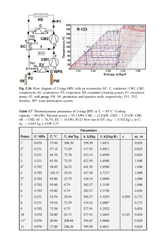
Fig. 5.36 Flow diagram of 2-stage HPU with an economizer EC. C, condenser; CM1, CM2,
           compressors; EC, economizer; EV, evaporator; HS, consumer’s heating system; P1, circulation
           pump; P2, well pump; PW, IW, production and injection wells, respectively; TV1, TV2,
           throttles; WP, water purification system.


           Table 5.7 Thermodynamic parameters of 2-stage HPU at T c ¼ 95 S. Cooling
           capacity ¼ 66 kWt; Thermal power ¼ 95.1 kWt; CM1 ¼ 12.8 kW; CM2 ¼ 3.25 kW; CM1
           eff. ¼ CM2 eff. ¼ 76.3%; EC ¼ 16 kWt; R123 flow rate in EV, _ m EV ¼ 0.542 kg=s, in C,
            _ m C ¼ 0.655 kg=s; COP 2.27.
                                            Parameters
                                        3
            Points  P, MPa  T, 8S  V,dm /kg  h, kJ/kg  S, kJ/(kg K)  x   _ m i = _ m
            1      0.076    27.00  206.26    399.58   1.6831             0.828
            2 00   0.231    57.18  71.69     417.55   1.6831             0.828
            2      0.231    64.39  73.78     423.14   1.6999             0.828
            3      0.231    63.56  73.55     422.50   1.6980             1.000
            4 00   0.702    98.69  24.25     441.50   1.6980             1.000
            4      0.702    105.31  25.03    447.40   1.7137             1.000
            5 00   0.702    95.00  23.79     438.19   1.6890             1.000
            5      0.702    95.00  0.79      302.27   1.3198             1.000
            6      0.702    95.00  0.79      302.27   1.3198             0.828
            7      0.231    52.58  20.94     302.27   1.3293      0.290  0.172
            8      0.231    59.58  72.39     419.41   1.6887             0.172
            9      0.702    72.58  0.75      277.91   1.2522             0.828
            10     0.076    20.00  65.73     277.91   1.2683      0.325  0.828
            11 00  0.076    20.00  200.68    394.67   1.6666             0.828
            11     0.076    27.00  206.26    399.58   1.6831             0.828