
Page 227 - Low Temperature Energy Systems with Applications of Renewable Energy
P. 227
214 Low-Temperature Energy Systems with Applications of Renewable Energy
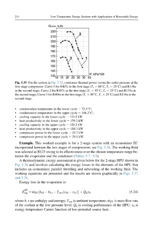
Fig. 5.35 For the system in Fig. 5.32, condenser thermal power versus the outlet pressure at the
first-stage compressor: Curve 1 for R407c in the first stage (T c ¼ 80 C, T e ¼ 25 C) and R134a
in the second stage; Curve 2 for R407c in the first stage (T c ¼ 95 C, T e ¼ 25 C) and R134a in
the second stage; Curve 3 for R404a in the first stage (T c ¼ 80 C, T e ¼ 25 C) and R134a in the
second stage.
• condensation temperature in the lower cycle e 72.4 S;
• condensation temperature in the upper cycle e 104.2 S;
• cooling capacity in the lower cycle e 133.5 kW
• heat productivity in the lower cycle e 159.2 kW
• cooling capacity in the upper cycle e 159.2 kW
• heat productivity in the upper cycle e 188.3 kW
• compressor power in the lower cycle e 25.7 kW
• compressor power in the upper cycle e 29.1 kW.
Example. This worked example is for a 2-stage system with an economizer EC
incorporated between the two stages of compression; see Fig. 5.36. The working fluid
was selected as R123 owing to its effectiveness over the chosen temperature range be-
tween the evaporator and the condenser (Tables 5.7e5.9).
A thermodynamic exergy assessment is given below for the 2-stage HPU shown in
Fig. 5.36 and involves calculating the exergy losses in the elements of the HPU that
includes an economizer, parallel throttling and subcooling of the working fluid. The
working equations are presented and the results are shown graphically in Figs. 5.37
and 5.38.
Exergy loss in the evaporator is:
E _ EV _ (5.24)
0
Dk ¼ _ m EV ½h 10 h 11 T env ðs 10 s 11 Þ þ Q s 0
where h, s are enthalpy and entropy; T env is ambient temperature; _ m EV is mass flow rate
_
of the coolant at the low pressure level; Q is cooling performance of the HPU; s 0 is
0
exergy temperature Carnot function of low-potential source heat.