
Page 265 - Low Temperature Energy Systems with Applications of Renewable Energy
P. 265
250 Low-Temperature Energy Systems with Applications of Renewable Energy
Table 6.4 Temperatures and mass flow rates at key points in the system shown in Fig. 6.22.
Temperature, Mass flow, Mass flow,
Location Item 8C t/h kg/s
1 Exchange water 15 710 197.2
2 Geothermal brine 145 1000 277.8
3 Produced hot water 115 800 222.2
4 Fresh water for dilution w15 250 69.4
5 Industrial consumption 115 300 83.3
6 Residential & general 85 750 208.3
usage
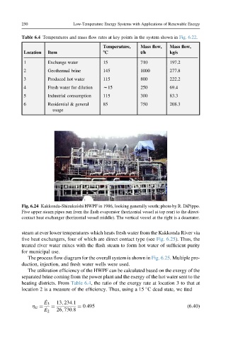
Fig. 6.24 Kakkonda-Shizukuishi HWPF in 1986, looking generally south; photo by R. DiPippo.
Five upper steam pipes run from the flash evaporator (horizontal vessel at top rear) to the direct-
contact heat exchanger (horizontal vessel middle). The vertical vessel at the right is a deaerator.
steam at ever lower temperatures which heats fresh water from the Kakkonda River via
five heat exchangers, four of which are direct contact type (see Fig. 6.25). Thus, the
treated river water mixes with the flash steam to form hot water of sufficient purity
for municipal use.
The process flow diagram for the overall system is shown in Fig. 6.25. Multiple pro-
duction, injection, and fresh water wells were used.
The utilization efficiency of the HWPF can be calculated based on the exergy of the
separated brine coming from the power plant and the exergy of the hot water sent to the
heating districts. From Table 6.4, the ratio of the exergy rate at location 3 to that at
location 2 is a measure of the efficiency. Thus, using a 15 C dead state, we find
_
E 3 13; 234:1
h ¼ ¼ ¼ 0:495 (6.40)
U _
E 2 26; 730:8