
Page 263 - Low Temperature Energy Systems with Applications of Renewable Energy
P. 263
248 Low-Temperature Energy Systems with Applications of Renewable Energy
Fig. 6.20 Kakkonda 50 MW Unit 1 as seen in 1979. Well pad B is in foreground with cyclone
separators at right and silencers at left; photo from H. Nakamura, 1978.
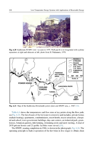
Fig. 6.21 Map of the Kakkonda-Shizukuishi power plant and HWPF area, c. 1987 [10].
Table 6.4 shows the temperatures and flow rates at key points along the flow path;
see Fig. 6.22. The list of users of the hot water is extensive and includes: private homes
(radiant heating), apartments, condominiums, resort hotels, tourist attractions, a hospi-
tal and school, town government buildings, day-care centers, an industrial park, green-
houses, botanical gardens, fish farming, swimming pools and snow melting. A total of
2670 private homes and 23 public facilities were served [10].
The HWPF, nearing completion in 1986, is shown in the photograph, Fig. 6.24. The
operating principle is flash evaporation of the hot brine in five stages to obtain clean